 |
 |
 |
 |
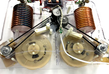 |
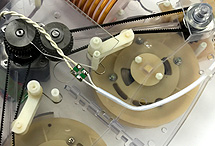
■Each element has home position sensor so that the controller detects the home position to stop movement. Two separate reels driven by gear
belts are used for elements. The reels are installed side by side which brings two major merit for VERSA antenna. One is that it reduces the floating capacitance between elements,
and the other is elements move smoothly without stress. |
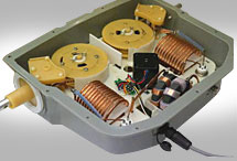
■Models that can be used on 7MHz have Hi-Q loading coil reducing the physical length about 30% for the band. The 4mm OD copper coil makes you possible to operate heavily like RTTY contest operation.
| ■The contact made of special alloy without cadmium that efficiently pass the transmitting power to the element. For the antennas with 7MHz, Hi-Q coil vacuum relays are employed. VERSA antenna works as full size antenna 10MHz and above. |
|
 |
 |
 |
 |
■The controller is designed user friendly, making for easy use. It has NORMAL, 180°,
and DIPOLE modes. Because the SWR changes depending on its circumstances, element lengths are adjustable.
You can fine tune the SWR at your location. KA-1 controller is equipped with a communication interface for most transceivers
in today’s market. To protect your amplifier and VERSA antenna, the controller has a protection circuit that opens the TX Ground
line between your amplifier and exciter while the elements are moving.
|
■The boom material is MIL standard aluminum, ensuring durability and corrosion resistance qualities. The plate that supports the elements is des
igned for maximum durability. To ensure proper element position, silicon rubber and high strength plastic holders are incorporated without adverse effects on higher bands.
|
■The antenna element supports are high strength fiber glass and are secured in place by means of clamps. This greatly reduces the gravitational
effects on the AEU. There are 2 models, depending on the radio frequency in use. One model is designed for 14MHz and above. This model is 5.2 meters long and is comprised of 3 sections
with a weight of about 1 Kg. The 7MHz and higher model is 7.4 meters long and is comprised of 4 sections with a weight of about 2.3 Kg. |
■Water proof connectors are preinstalled with the junction cable and the control cable, saving time and ensuring proper connectivity.
Wiring size and type are designed for this application. The end user needs only to determine cable length required.
|
 |
 |
|
■Controller interface
・Power connector ・CI-V(3.5mm monophonic) ・Linear AMP(RCA) ・PC⇔RIG(Toggle) ・Transceiver(RCA) ・USB(Type-B)
・Antenna Connection(Amphenol36P) ・RC232C(D-sub9pin)
■Models confirmed working with VERSA BEAM
[KOHJINSHA] KL-1 / [KENWOOD] TS-990,TS-590,TS2000、etc / [YAESU] FTDX-9000,FTDX-5000,FT-2000、etc
[ICOM] IC7800,IC7700,IC-7600、etc
[ELECRAFT] K2,K3 |
|
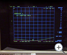
| ■SMITH CHART KA1-406 at 14MHz |
■SWR KA1-406 at 14MHz |
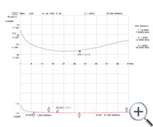
■Balun characteristic chart |
|
 |
 |
 |
 |
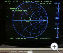
| The above Smith Chart shows the KA1-406's 14MHz measurement by HP8752C. You see both impedance and reactance are within the best position. |
The above KA1-406 SWR chart is measured at 14MHz. Measuredfrequency is fixed in above case:Note the SWR is below 1:1.5 with in the band. VERSA antenna elements (10MHz and above) move every 50 KHz and incorporate full length elements, allowing the SWR to remain below 1:1.5 at all points of the bands. |
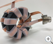
Both independent Balance-Unbalance (balun) and 9:4 impedance matching transformers are built utilizing properly matched Toroidal cores ensuring continuous duty cycle. Both characteristics are shown above. The upper display is the matching transformer and the bottom display is the balun. 7MHz through 50MHz the SWR is below 1:1.1 ensuring unwanted power loss from the coaxial cable. |
|
|


